Refine Your Search

Topic

Author

Affiliation

Search Results

Viewing 1 to 20 of 15871
Standard

"Startle Effect" and Crew Performance

2019-05-24
WIP
ARP7218
The scope of this ARP, "Startle Effect" and Crew Performance, includes pilots of turbine powered transport category aircraft and may also pertain to general aviation, the military, and/or other sectors of aircraft operations. It is focused on flight crews certified by the United States, however, may also pertain to crews certified by other countries. The scope describes all phases of training (initial, recurrent, upgrade, remedial, and operational) in both domestic and international flight operations, with the intent of assisting flight crews in responding to "startle effect".
Technical Paper

10 KWe Dual-Mode Space Nuclear Power System for Military and Scientific Applications

1992-08-03
929072
A 10 KWe dual-mode space power system concept has been identified which is based on INEL's Small Externally-fueled Heat Pipe Thermionic Reactor (SEHPTR) concept. This power system will enhance user capabilities by providing reliable electric power and by providing two propulsion systems; electric power for an arc-jet electric propulsion system and direct thrust by heating hydrogen propellant inside the reactor. The low thrust electric thrusters allow efficient station keeping and long-term maneuvering. The direct thrust capability can provide tens of pounds of thrust at a specific impulse of around 730 seconds for maneuvers that must be performed more rapidly. The direct thrust allows the nuclear power system to move a payload from Low Earth Orbit (LEO) to Geosynchronous Earth Orbit (GEO) in less than one month using approximately half the propellant of a cryogenic chemical stage.
Journal Article

2-Stroke High Speed Diesel Engines for Light Aircraft

2011-09-11
2011-24-0089
The paper describes a numerical study, supported by experiments, on light aircraft 2-Stroke Direct Injected Diesel engines, typically rated up to 110 kW (corresponding to about 150 imperial HP). The engines must be as light as possible and they are to be directly coupled to the propeller, without reduction drive. The ensuing main design constraints are: i) in-cylinder peak pressure as low as possible (typically, no more than 120 bar); ii) maximum rotational speed limited to 2600 rpm. As far as exhaust emissions are concerned, piston aircraft engines remain unregulated but lack of visible smoke is a customer requirement, so that a value of 1 is assumed as maximum Smoke number. For the reasons clarified in the paper, only three cylinder in line engines are investigated. Reference is made to two types of scavenging and combustion systems, designed by the authors with the assistance of state-of-the-art CFD tools and described in detail in a parallel paper.
Book

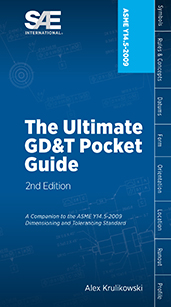
2009 Ultimate GD&T Pocket Guide 2nd Ed

2017-03-27
The Ultimate GD&T Pocket Guide explains the most common rules, symbols, and concepts used in geometric dimensioning and tolerancing. ...This one-of-a-kind reference guide includes over 100 detailed drawings to illustrate concepts, more than 40 charts for quick reference, explanations of each GD&T symbol and modifier and much more...Written by standards expert Alex Krulikowski, this valuable on-the-job reference clarifies how to interpret standard-compliant technical drawings that use ASME Y14.5-2009.
Book

2016 Mobility Engineering Professionals Salary Survey

2016-07-14
EXCLUSIVE MEMBER BENEFIT: 2016 MOBILITY ENGINEERING PROFESSIONAL SALARY SURVEY AND CALCULATOR Gain better insight into compensation practices: this salary survey is the only study its kind to explore levels and changes in compensation and employment for engineers and technical employees in the automotive, aerospace, and commercial vehicle industries. It benchmarks compensation levels based by geography, education, industry sector, experience, and managerial and budgetary responsibility. The full report is available to SAE International members by signing into your My SAE account and downloading it into your My Library area. Members also have full access to the updated online interactive salary calculator by visiting SAE’s website. Become a member of SAE International to access this exclusive benefit for free, or purchase it today. YOU BELONG HERE. Membership helps you succeed both personally and professionally. Join us today.
Technical Paper

21st Century Lunar Exploration: Advanced Radiation Exposure Assessment

2006-07-17
2006-01-2106
On January 14, 2004 President George W Bush outlined a new vision for NASA that has humans venturing back to the moon by 2020. With this ambitious goal, new tools and models have been developed to help define and predict the amount of space radiation astronauts will be exposed to during transit and habitation on the moon. A representative scenario is used that includes a trajectory from LEO to a Lunar Base, and simplified CAD models for the transit and habitat structures. For this study galactic cosmic rays, solar proton events, and trapped electron and proton environments are simulated using new dynamic environment models to generate energetic electron, and light and heavy ion fluences. Detailed calculations are presented to assess the human exposure for transit segments and surface stays.
Technical Paper

250 °C SiC Power Module Package Design

2008-11-11
2008-01-2892
In order to take full advantage of SiC, a high temperature package for power module using SiC devices was designed, developed, fabricated and tested. The details of the material selection and fabrication process are described. High temperature reliability test and power test shows that the package presented in this paper can perform well at the high junction temperature.
Technical Paper

270-Vdc/Hybrid 115-Vac Electric Power Generating System Technology Demonstrator

1991-09-01
912051
Sundstrand is investigating 270-Vdc/hybrid 115-Vac electrical power generating and distribution systems technology so as to be well prepared to offer such systems for future aircraft applications. The approach taken has been to design, build, and test a representative system that meets or exceeds the tightest of the performance standards as defined by miliary standards. This paper describes a single-channel, 120-kW hybrid system and presents some typical performance data. The dc bus supplies a 30-kVA, 400-Hz, 115-Vac inverter; constant power load banks of up to 150 kW; and a resistive load bank of up to 90 kW. System simulation studies indicated the potential for unstable operation due to the negative impedance of the constant power load in conjunction with the source ripple filter and the load EMI filters. Unstable voltage and current were observed in system testing when the magnitude of the source impedance was not sufficiently below that of the load impedance.
Technical Paper

270-Vdc/Hybrid 115-Vac Electric Power Generating System Technology Demonstrator Evolution to a Dual-Channel, More Electric Aircraft Technology Development Testbed

1991-09-01
912183
Sundstrand has been investigating 270-Vdc/hybrid 115-Vac electrical power generating systems (EPGS) technology in preparation for meeting the electrical power generating system (EPGS) requirements for future aircraft (1). Systems such as the one being investigated are likely to be suitable for the More-Electric Aircraft (MEA) concepts presently under industry and military study. The present Sundstrand single-channel testbed is being further expanded to better understand the electrical system performance characteristics and power quality requirements of an MEA in which traditional mechanical subsystems are replaced by those of a “more-electric” nature. This paper presents the most recent Sundstrand 270-Vdc system transient performance data, and describes the modifications being made to the 270-Vdc/hybrid 115-Vac testbed.
Technical Paper

2D Ice Shape Scaling for Helicopter Blade Profiles in Icing Wind Tunnel

2015-06-15
2015-01-2129
Different Airbus Helicopters main rotor blade profiles were tested in different icing wind tunnels and for different icing conditions. One of the objectives of the accretion tests was to validate the use of 2D icing scaling laws established for fixed wing aircraft on helicopter blade profiles. Therefore, ice shapes resulting from tests with the same icing similarity parameters are compared to each other allowing the assessment of icing scaling laws for helicopter applications. This paper presents the icing scaling laws used at Airbus Helicopters on blade profiles, the different test set ups and test models and it presents the comparison of the ice shapes collected during the icing wind tunnel test campaigns.
Technical Paper

2D Polar Assessment in Icing Wind Tunnel for iced Helicopter Blade Profiles

2015-06-15
2015-01-2127
A helicopter blade profile was tested in the DGA Aero-engine Testing's icing altitude test facility S1 in Saclay, France during the winter of 2013/2014. The airfoil was a helicopter main rotor OA312 blade profile made out of composite material and with a metallic erosion shield. Dry air and ice accretion tests have been performed in order to assess the iced airfoil's aerodynamic behaviour. Several icing conditions were tested up through Mach numbers around 0.6. This paper presents the test setup, the test model and some of the test results. The test results presented in this paper include the ice shapes generated as well as dry air and iced airfoil lift and drag curves (polars) which were obtained with the real ice shapes on the airfoil.
Technical Paper

3 Inch Ice Shapes, AB Initio

2023-06-15
2023-01-1434
The term “3 inch ice shapes” has assumed numerous definitions throughout the years. At times it has been used to generally characterize large glaze ice accretions on the major aerodynamic surfaces (wing, horizontal stabilizer, vertical stabilizer) for evaluating aerodynamic performance and handling qualities after a prolonged icing encounter. It has also been used as a more direct criterion while determining or enforcing sectional ice shape characteristics such as the maximum pinnacle height. It is the authors’ observation that over the years, the interpretation and application of this term has evolved and is now broadly misunderstood. Compounding the situation is, at present, a seemingly contradictory set of guidance among (and even within) the various international regulatory agencies resulting in an ambiguous set of expectations for design and certification specialists.
Technical Paper

3-Dimensional Lightning Observations Using a Time-of-Arrival Lightning Mapping System

2001-09-11
2001-01-2881
A lightning mapping system has been developed that locates the sources of VHF radiation from lightning discharges in three spatial dimensions and time. The system consists of several VHF receivers distributed over an area of about 100 km diameter. The system locates VHF radiation sources over the array with an accuracy of about 100 m. The system locates sources out to 250 km from the center of the array with reduced accuracy. The observations are found to reflect the basic charge structure of electrified storms.
Technical Paper

3D Computational Methodology for Bleed Air Ice Protection System Parametric Analysis

2015-06-15
2015-01-2109
A 3D computer model named AIPAC (Aircraft Ice Protection Analysis Code) suitable for thermal ice protection system parametric studies has been developed. It was derived from HASPAC, which is a 2D anti-icing model developed at Wichita State University in 2010. AIPAC is based on the finite volumes method and, similarly to HASPAC, combines a commercial Navier-Stokes flow solver with a Messinger model based thermodynamic analysis that applies internal and external flow heat transfer coefficients, pressure distribution, wall shear stress and water catch to compute wing leading edge skin temperatures, thin water flow distribution, and the location, extent and rate of icing. In addition, AIPAC was built using a transient formulation for the airfoil wall and with the capability of extruding a 3D surface grid into a volumetric grid so that a layer of ice can be added to the computational domain.
Technical Paper

3D Image Metrology for Lean Manufacturing

1999-06-05
1999-01-2290
The need to improve quality while reducing cost in aerospace manufacturing is requiring new manufacturing methods and processes. Advanced technologies, such as 3D Image Metrology, offer great potential to lean manufacturing, if properly integrated into the production process. Over the last years 3D Image Metrology has developed a level of performance, which make it ideally suited for this purpose. These capabilities include the automatic in-process inspection of tools and parts before machining, machine control for highly accurate positioning during the machining operation, and in-process inspection during machining. This offers jig-less assembly, lower inventory, faster part throughput, and many more advantages.
Technical Paper

3D Immersed Boundary Methods for the Calculations of Droplet Trajectories towards Icing Application

2023-06-15
2023-01-1458
The in-flight ice accretion simulations are typically performed using a quasi-steady formulation through a multi-step approach. As the ice grows, the geometry changes, and an adaptation of the fluid volume mesh used by the airflow and droplet-trajectory solver is required. Re-meshing or mesh deformation are generally employed to do that. The geometries formed are often complex ice shapes increasing the difficulty of the re-meshing process, especially in three-dimensional simulations. Consequently, difficulties are encountered when trying to automate the process. Contrary to the usual body-fitted mesh approach, the use of immersed boundary methods (IBMs) allows solving, or greatly reducing, this problem by removing the mesh update, facilitating the global automation of the simulation. In the following paper, an approach to perform the airflow and droplet trajectory calculations for three-dimensional simulations is presented. This framework utilizes only immersed boundary methods.
Standard

3GCN - SEAT DISTRIBUTION SYSTEM

2014-08-15
CURRENT
ARINC809-3
This specification defines general architectural philosophy and specific design guidance for the proper installation and interface of various cabin equipment within the seats. Consistency with this specification allows each component installed on the seat to operate in concert when integrated with other relevant cabin type equipment. Standard electrical and mechanical interfaces of the In- Flight Entertainment System (IFES) equipment for the 3rd Generation Cabin Network (3GCN) associated with the seat are defined. This equipment consists of the headphone jacks (HPJ), passenger control unit (PCU)/multi function handset (including the cord), seat video display (SVD), remote data outlet (RDO), integrated seat box (ISB) which includes the seat power box (SPB)/seat data box (SDB), remote power outlet (RPO), and in-seat cables. Appropriate definitions are also provided for other electrical devices associated with the seat control/position mechanism.
Standard

400 Hz CONNECTION AIRCRAFT ELECTRICAL MAINTENANCE PROCEDURES

1994-12-01
HISTORICAL
AIR4365
This SAE Aerospace Information Report (AIR) describes field-level procedures to determine if 400 Hz electrical connections for external power may have been subjected to excessive wear, which may result in inadequate disengagement forces.
Standard

400 Hz Connection Aircraft Electrical Maintenance Procedures

2008-03-28
HISTORICAL
AIR4365A
This SAE Aerospace Information Report (AIR) describes field-level procedures to determine if 400 Hz electrical connections for external power may have been subjected to excessive wear, which may result in inadequate disengagement forces.
X